Bonjour,
Je possède comme controleur de vol une carte Multiwii mega pro EZ3.0 de chez Readytoflyquad.
C'est cette carte: http://www.readytoflyquads.com/multiwii ... gps-option" onclick="window.open(this.href);return false;
J'ai acheté une minimosd, celle là: http://www.ebay.fr/itm/GoolRC-OSD-Compa ... Sw0fhXmdDZ" onclick="window.open(this.href);return false;
J'ai flashé la carte avec les fichiers du lien http://www.mwosd.com" onclick="window.open(this.href);return false; après avoir configuré le fichier config.h (multiwii, etc....)
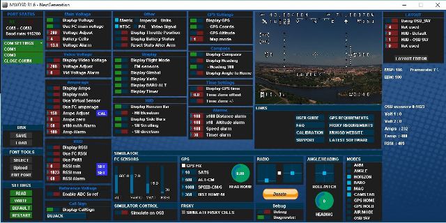
Avec le GUI, j'ai parametré ce que je voulais afficher.
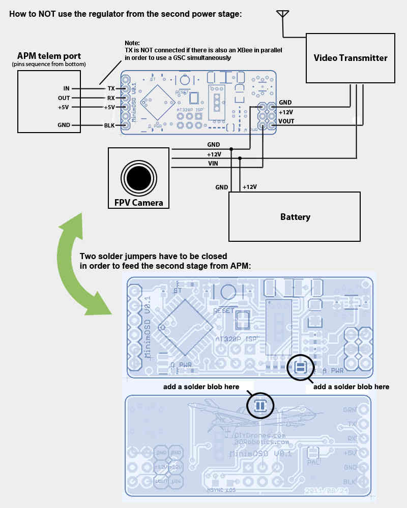
J'ai connecté le +5v, le Gnd de la multiwii au 5V et Gnd de la miniOSD. J'ai connecté le TX au RX et vice versa. La video de la caméra est connecté au video IN de la minimOSD et la sortie video de la minimOSD au TX Fatshark. Toute la chaine est bien parametrée en NTSC (cavalier PAL sur la minimosd non soudé).
Et la il y a une chose qui ne va pas. Je n'ai pas la video, meme pas la "neige".
Si je connecte directement la CAM au TX Fatshark, j'ai bien l'image.
Donc en gros, c'est quoi qui bloque? Faut-il parametrer quelque chose dans le config.h de la Mega Pro EZ3?
J'ai un module Bluetooth sur le serial0 , le GPS sur le serial 2 et l'OSD sur le serial 3.
Faut t'il relier le 12V de la sortie video de la minimosd au 12V de la batterie comme expliqué ici : https://github.com/ShikOfTheRa/scarab-o ... ION/FAQ.md" onclick="window.open(this.href);return false; ( "If using MinimOSD board make sure your output stage is properly powered.")
Merci pour l'aide que vous pourrez m'apporter.
A plus
Jacques
minimosd ecran noir
Modérateur : Dehas
-
dujack

- Quadricopter
- Messages : 150
- Enregistré le : lun. 19 oct. 2015 16:46
- Réputation : 0
-
Dehas

- Administrateur du site
- Messages : 16171
- Enregistré le : ven. 3 juin 2011 12:50
- Réputation : 5
- Localisation : Saint Dié des Vosges
- Genre :
- Contact :
-
dujack
- Quadricopter
- Messages : 150
- Enregistré le : lun. 19 oct. 2015 16:46
- Réputation : 0
Re: minimosd ecran noir
Salut dehas,
Non, ca correspond a quoi c'est deux points a souder?
Ma camera est une 600vtl de fatshark, donc en 5V.
Non, ca correspond a quoi c'est deux points a souder?
Ma camera est une 600vtl de fatshark, donc en 5V.
-
Dehas
- Administrateur du site
- Messages : 16171
- Enregistré le : ven. 3 juin 2011 12:50
- Réputation : 5
- Localisation : Saint Dié des Vosges
- Genre :
- Contact :
-
dujack
- Quadricopter
- Messages : 150
- Enregistré le : lun. 19 oct. 2015 16:46
- Réputation : 0
Re: minimosd ecran noir
Merci pour ta reponse tres claire... Je fais ca demain et je donne des nouvelles...
-
dujack
- Quadricopter
- Messages : 150
- Enregistré le : lun. 19 oct. 2015 16:46
- Réputation : 0
Re: minimosd ecran noir
Finalement je viens de faire les deux soudures et pas mieux. J'ai la deuxieme led rouge qui s'allume mais toujours un ecran noir.
Si tu as une autre piste, je suis preneur.
Si tu as une autre piste, je suis preneur.
-
Dehas
- Administrateur du site
- Messages : 16171
- Enregistré le : ven. 3 juin 2011 12:50
- Réputation : 5
- Localisation : Saint Dié des Vosges
- Genre :
- Contact :
Re: minimosd ecran noir
il y a certain minimosd qui ont un mauvais affichage a l’arrière, inverse le in et le out.
Tu n'as pas une led bleu ou verte qui clignote ??
Tu n'as pas une led bleu ou verte qui clignote ??
-
dujack
- Quadricopter
- Messages : 150
- Enregistré le : lun. 19 oct. 2015 16:46
- Réputation : 0
-
dujack
- Quadricopter
- Messages : 150
- Enregistré le : lun. 19 oct. 2015 16:46
- Réputation : 0
-
Dehas
- Administrateur du site
- Messages : 16171
- Enregistré le : ven. 3 juin 2011 12:50
- Réputation : 5
- Localisation : Saint Dié des Vosges
- Genre :
- Contact :
Re: minimosd ecran noir
Sur le tiens elle est jaune, pas grave, si elle clignote rapidement c'est que ça fonctionne.
Reprends tout depuis le début, connexion etc...
Reprends tout depuis le début, connexion etc...
-
dujack
- Quadricopter
- Messages : 150
- Enregistré le : lun. 19 oct. 2015 16:46
- Réputation : 0
Re: minimosd ecran noir
J'ai deja verifié le cablage mais je reprendrai tout a zero demain.
Par contre, pourquoi les cartes minimosd sont livree sans les deux plots de soudures non fait?
Par contre, pourquoi les cartes minimosd sont livree sans les deux plots de soudures non fait?
-
opossome64

- Pilote toutes catégories
- Messages : 907
- Enregistré le : jeu. 17 oct. 2013 18:22
- Réputation : 0
- Localisation : Plus au sud ...
Re: minimosd ecran noir
Oups , pas vu le nouveau sujet ...
Les plots c'est pour alimenter le Max7456 (la vidéo) , soit par le coté 5V (carte de vol) du miniosd avec les plots soudés, soit par le coté 12V (camera) sans les plots soudés .
Donc pas soudés pour laisser le choix à l'utilisateur , les micro MinimOsd n'ont pas cette option , tout en 5V et c'est très bien , en 12V ça chauffe ... mais si tu as mis du 12V (ou même du 5V) par le coté camera avec les plots soudés , le Max7456 est probablement mort ...
Bon courage !
- SpeedRacer 210 - RS2205 - XM20A - SP3 Betaflight
- QX90
- Optic6 2.4Ghz FRSky
- BaseSD + VRX + faceplate mod
Chaine Youtube
- QX90
- Optic6 2.4Ghz FRSky
- BaseSD + VRX + faceplate mod
Chaine Youtube
-
dujack
- Quadricopter
- Messages : 150
- Enregistré le : lun. 19 oct. 2015 16:46
- Réputation : 0
Re: minimosd ecran noir
Non, côté minimosd je n'ai relié que le gnd, rx, tx et 5V ainsi que Vin, Vout et les deux gnd côté Caméra...
-
opossome64
- Pilote toutes catégories
- Messages : 907
- Enregistré le : jeu. 17 oct. 2013 18:22
- Réputation : 0
- Localisation : Plus au sud ...
Re: minimosd ecran noir
Tu peux émuler la carte de vol avec le FTDI + GUI , avec un écran ou un vtx au fesse tu devrais voir bouger des trucs .
Truc bête en parlant du GUI , t'as uploadé la table de caractère dans le MAX7456 alimenté (avec les ponts soudés) ?
Si pas de table de caractère , pas d'affichage ...
Truc bête en parlant du GUI , t'as uploadé la table de caractère dans le MAX7456 alimenté (avec les ponts soudés) ?
Si pas de table de caractère , pas d'affichage ...
- SpeedRacer 210 - RS2205 - XM20A - SP3 Betaflight
- QX90
- Optic6 2.4Ghz FRSky
- BaseSD + VRX + faceplate mod
Chaine Youtube
- QX90
- Optic6 2.4Ghz FRSky
- BaseSD + VRX + faceplate mod
Chaine Youtube
-
dujack
- Quadricopter
- Messages : 150
- Enregistré le : lun. 19 oct. 2015 16:46
- Réputation : 0
Re: minimosd ecran noir
Parfois les choses qui semblent bêtes sont utiles 
J'ai bien uploadé les fonts mais les ponts non réalisés (j'ai fait les ponts hier soir avant d'aller me pieuter et donc j'ai pas refait le paramétrage GUI).
Je referai ça ce soir en rentrant. J'espère que c'est ça.
Je te tiens au courant....
Encore merci pour ton aide...
J'ai bien uploadé les fonts mais les ponts non réalisés (j'ai fait les ponts hier soir avant d'aller me pieuter et donc j'ai pas refait le paramétrage GUI).
Je referai ça ce soir en rentrant. J'espère que c'est ça.
Je te tiens au courant....
Encore merci pour ton aide...
-
dujack
- Quadricopter
- Messages : 150
- Enregistré le : lun. 19 oct. 2015 16:46
- Réputation : 0
Re: minimosd ecran noir
Bon, j'ai tout repris de zéro y compris le cablage, tout reflashé et uploadé les font avec la puce video alimentée mais toujours ecran noir.
Voic ma config dans le GUI
Voici mon fichier config.h de la minimosd
et celui de mon multiwii
Si tu vois quelque chose d'anormal, je suis preneur.... Mais je pense à un probleme avec mon serial3 qui ne doit rien envoyer
A plus
Jacques
Voic ma config dans le GUI

Voici mon fichier config.h de la minimosd
Code : Tout sélectionner
/*--------------------------       MANDATORY configurable parameters      ----------------------------------------------------*/
/*--------------------------       MANDATORY configurable parameters      ----------------------------------------------------*/

/********************       OSD HARDWARE settings      *********************/
//Choose ONLY ONE option:
#define MINIMOSD                    // Uncomment this if using standard MINIMOSD hardware (default for 95% of boards)
//#define WITESPYV1                 // Uncomment this if using Witespy V1.1 OSD, select this to correct for both swapped bat1/bat 2 and to also use alternative resistors / pinouts.
//#define WITESPYMICRO              // Uncomment this if using Witespy Micro Minim OSD, select this to correct for swapped bat1/bat 2.
//#define RUSHDUINO                 // Uncomment this if using Rushduino

// NOTE-some of the popular RTFQ/Witespy boards have swapped bat1/bat2 pins and alternative voltage measuring resistors
// If having difficulties, first select default MINIMOSD as above, then use the following to correct:
// #define SWAPVOLTAGEPINS          // For boards with batt voltage appearing on vid voltage
// #define ALTERNATEDIVIDERS        // For boards with voltage unable to be adjusted high enough


/********************       CONTROLLER SOFTWARE      *********************/
// Choose ONLY ONE option:-
// Note - choose carefully to ensure correct settings are written to flight controller.
// The first three are for convenience - they set the OSD for the latest FC version.
// IMPORTANT - remember to update MWOSD when updating FC software!!

// Choose ONLY ONE option from the following long list :-

// latest release...
#define MULTIWII                  // Uncomment this if you are using latest MULTIWII version from repository (2.4 at time of this MWOSD release)
//#define BASEFLIGHT                // Uncomment this if you are using latest BASEFLIGHT version from repository (Stable 2015.08.27 at time of this MWOSD release)
//#define TAULABS                   // Uncomment this if you are using the latest Tau Labs MSP Module
//#define CLEANFLIGHT               // Uncomment this if you are using latest CLEANFLIGHT version from repository (1.11.0 at time of this MWOSD release)
//#define BETAFLIGHT                // Uncomment this if you are using BETAFLIGHT (same as CLEANFLIGHT t time of this MWOSD release)
//#define HARIKIRI                  // Uncomment this if you are using HARIKIRI (for BOXNAMES compatibility)
//#define NAZA                      // Uncomment this if you are using NAZA flight controller
//#define GPSOSD_UBLOX              // Uncomment this if you are using a UBLOX GPS module for a GPS based OSD
//#define GPSOSD_NMEA               // Uncomment this if you are using a NMEA compatible GPS module for a GPS based OSD
//#define GPSOSD_MTK                // Uncomment this if you are using a MTK module for a GPS based OSD
//#define NOCONTROLLER              // Uncomment this if you ahave nothing connected to the serial port - no controller or GPS module
// old releases supported...
//#define MULTIWII_V23              // Uncomment this if you are using MW versions 2.2/2.3
//#define MULTIWII_V21              // Uncomment this if you are using MW versions 2.0/2.1  (for BOXNAMES compatibility)
//#define BASEFLIGHT20150327        // Uncomment this if you are using BASEFLIGHT up to and including version Stable 2015.03.27
//#define CLEANFLIGHT172            // Uncomment this if you are using CLEANFLIGHT versions up to and including 1.7.2
//#define CLEANFLIGHT180            // Uncomment this if you are using CLEANFLIGHT versions 1.8.0 & 1.8.1


/********************       AIRCRAFT/INSTALLATION TYPE settings      *********************/
//Choose ONLY ONE option:
#define ROTORCRAFT                  // Default for multirotors etc.
//#define FIXEDWING                 // Uncomment this if you are using fixed wing MultiWii or Baseflight


/*--------------------------       OPTIONAL configurable parameters      ----------------------------------------------------*/
/*--------------------------       OPTIONAL configurable parameters      ----------------------------------------------------*/

/********************       GPS OSD settings      *********************/
//#define OSD_SWITCH_RSSI           // Enables 3 way screen switch using a TX channel via a RX channel connected to the OSD RSSI pin. Typically used for GPSOSD.
//#define PWMTHROTTLE               // Enables throttle feature, virtual current sensor using RC throttle connected into OSD RSSI pin. Calibrate throttle using GUI RSSI cal functions

//#define PPMOSDCONTROL             // Enables full OSD menu, screen switching, RSSI, Throttle feature, virtual current sensor, etc using a PPM signal into OSD RSSI pin. Requires TX type to be set below.
//#define SERIAL_SUM_PPM_RHF        // Enable for Robe/Hitec/Futaba
//#define SERIAL_SUM_PPM_GS         // Enable for Graupner/Spektrum
//#define SERIAL_SUM_PPM_M          // Enable for Multiplex
//#define SERIAL_SUM_PPM_HS         // Enable for Hitec/Sanwa


/********************       FILTER settings      *********************/
//Choose ONLY ONE option:
#define STAGE2FILTER                // Enable for smoother readings of voltage / current / RSSI.
//#define SMOOTHFILTER              // Enable for smoothest readings of voltage / current / RSSI. Uses more memory. Prototype


/********************       RSSI settings (PWM/PPM)      *********************/
//Choose ONLY ONE option:
//Note all require PWM RSSI to be enabled on GUI
#define INTPWMRSSI                  // Undefine this to use new interrupt PWM RSSI method (standard PWM 0-2000ms pulse width)
//#define PULSEINPWMRSSI            // DEPRECATED Undefine this to use legacy non interrupt PWM RSSI method (pulse width 0 - 2000ms pulse width)
//#define FASTPWMRSSI               // Undefine this to use high PWM refresh frequency RSSI (greataer than standard 50 hz)
//#define RCRSSI 3                  // Undefine this to use RC channel (0-7) for RSSI (this can be from the FC - or a PPM channel with GPSOSD)


/********************       GPS settings      *********************/
#define MINSATFIX 5                 // Number of sats required for a fix. 5 minimum. More = better


/********************       WARNING/STATUS settings      *********************/
#define SATACTIVECHECK              // Alerts if sats below MINSATFIX - in addition to flashing sat indicator
#define GPSACTIVECHECK 5            // Alerts if no GPS data for more than x secs. Sets GPS sats to zero
#define MSPACTIVECHECK 3            // Alerts if no Flight controller data for more than x secs.
#define DISP_LOW_VOLTS_WARNING      // Alerts with additional text warning if low voltage
#define FORCE_DISP_LOW_VOLTS        // Enable display low voltage warning override for screen layouts where its disabled
//#define FORCE_DISP_LOW_VID_VOLTS  // Enable display low VIDEO voltage warning override for screen layouts where its disabled


/********************       AIRCRAFT type=FIXEDWING settings      *********************/
// **ONLY** valid when using fixed wing
//#define USEMAGHEADING             // Undefine this to use MAG for FW heading instead of GPS (requires controller with MAG sensor)
//#define USEBAROALTITUDE           // Undefine this if you have a BARO to use BARO for FW altitude instead of GPS (requires controller with BARO sensor) ** Recommended **
//#define USEGLIDESCOPE 40          // Enables ILS glidescope where 40 = 4.0° glidescope. 1.0 deg gradiented scope scale requires enabling in layouts
//#define DISABLEGPSALTITUDERESET   // Disables automatic reset of GPS Altitude to zero at arm for FC that already provide this functionality.
//#define LONG_RANGE_DISPLAY        // Enable this to for long range display consolidation - displays distance in KM or feet when exceed 9999m or ft


/******************** Serial speed settings *********************/
// Choose ONLY ONE option:
#define BAUDRATE 115200
//#define BAUDRATE 57600
//#define BAUDRATE 38400
//#define BAUDRATE 19200
//#define BAUDRATE 9600


/******************** Serial MSP speed settings *********************/
// Choose ONLY ONE option: increases speeds of serial update - but with impact to flight controller
//#define MSP_SPEED_LOW     // Enable for soft serial / slow baud rates.
#define MSP_SPEED_MED       // Default
//#define MSP_SPEED_HIGH    // Enable for faster AHI and speed updates. Requires higher baud rates and increases overhead on the FC to process


/********************       CALLSIGN settings      *********************/
#define   CALLSIGNINTERVAL 60      // How frequently to display Callsign (in seconds)
#define   CALLSIGNDURATION 4       // How long to display Callsign (in seconds)
//#define CALLSIGNALWAYS           // Alternative option - enable to permanently display callsign.
//#define FREETEXTLLIGHTS          // Alternative option - enable to display freetext (or callsign) when LLIGHTS Switch active on TX.
//#define FREETEXTGIMBAL           // Alternative option - enable to display freetext (or callsign) when GIMBAL Switch active on TX.


/********************       STARTUP settings      *********************/
//#define INTRO_VERSION               "MWOSD - DEV 1.6.0.0" // Call the OSD something else if you prefer. KVOSD is not permitted - LOL.
//#define INTRO_CALLSIGN            // Enable to display callsign at startup
//#define INTRO_TIMEZONE            // Enable to display timezone at startup - if GPS TIME is enabled
//#define INTRO_DELAY 5             // Seconds intro screen should show for. Default is 8
#define INTRO_MENU                  // Enable to display TX stick MENU
//#define STARTUPDELAY 2000         // Enable alternative startup delay (in ms) to allow MAX chip voltage to rise fully and initialise before configuring


/********************       I2CGPS type settings      *********************/
//#define I2CGPS_SPEED              // Uncomment this if you are using older I2CGPS - and need to correct for speed error (10x too slow)
//#define I2CGPS_DISTANCE           // Uncomment this if you are using older I2CGPS - and need to correct for distance error (650m max) UNTESTED


/********************       MAP MODE Settings       *********************/
//#define MAPMODENORTH              // Enable to use North as MAP reference in MODE 1 instead of take off direction (Default = disable)


/********************       FEATURES      *********************/
// Disable features if you require memory for other features
// Further configuration may be require elsewhere in config.h + option enabled on GUI
//#define SBDIRECTION     // Enable/disable sidebar indicators (changes in speed or altitude)
//#define HORIZON         // Enable/disable HORIZON indicator
//#define MAPMODE         // Enable/disable MAP MODE - map indication of relative positions of home and aircraft
//#define GPSTIME       // Enable/disable GPS Time functions
//#define SPORT         // Enable/disable FRSKY S.PORT cell code


/********************       Display Settings         ************************/
#define MAXSTALLDETECT              // Enable to attempt to detect MAX chip stall from bad power. Attempts to restart.
//#define AUTOCAM                   // Disable if no screen display. Enables autodetect Camera type PAL/NTSC. Overrides GUI/OSD settings.
//#define AUTOCAMWAIT               // **UNTESTED** - Use with AUTOCAM - waits until camera is ready - i.e. if power up cameras after FC.
#define DECIMAL '.'                 // Decimal point character, change to what suits you best (.) (,)
#define USE_VSYNC                   // Disable if no screen display. Removes sparklies as updates screen during blanking time period.
//#define SHIFTDOWN                 // Select if your monitor cannot display top line fully. It shifts top 3 lines down. Not suitable for all layouts
//#define ALT_CENTER                // Enable alternative center crosshair
//#define FORCECROSSHAIR            // Forces a crosshair even if no AHI / horizon used
//#define HIDEARMEDSTATUS           // Enable to hide ARMED / DISARMED status
//#define HIDESUMMARY               // Enable to suspend display of summary screen when disarming
//#define SHORTSUMMARY              // Display only timer on flight summary
//#define FASTPIXEL                 // Optional - may improve resolution - especially hi res cams
//#define WHITEBRIGHTNESS 0x00      // Optional change from default 0x00=120%,0x01=100%,0x10=90%,0x11=80%  default is 0x01=100%
//#define BLACKBRIGHTNESS 0x00      // Optional change from default 0x00=0%,0x01=10%,0x10=20%0x11=30%  default is 0x00=0%
//#define I2CERROR 3                // Autodisplay Mutltiwii I2C errors if exceeds specified count
//#define NOTHROTTLESPACE           // Enable to remove space between throttle symbol and the data
//#define DISPLAY_PR                // Display pitch / roll angles. Requires relevant layout ppositions to be enabled
//#define FULLAHI                   // Enable to display a slightly longer AHI line
//#define REVERSEAHI                // Reverse pitch / roll direction of AHI - for DJI / Eastern bloc OSD users
//#define AHICORRECT 10             // Enable to adjust AHI on display to match horizon. -10 = -1 degree
#define AHIPITCHMAX 200             // Specify maximum AHI pitch value displayed. Default 200 = 20.0 degrees
#define AHIROLLMAX  400             // Specify maximum AHI roll value displayed. Default 400 = 40.0 degrees
#define AHILEVEL                    // Enable to display AHI level indicators on sidebars
#define APINDICATOR                 // Enable to display AUTOPILOT instead of RTH distance
#define GUISENSORS                  // Enable if wish to view raw sensor data on GUI
//#define DISPLAYWATTS              // Enable this to display Watts (if selected in layouts)
//#define LONG_RANGE_DISPLAY        // Enable this to for long range display consolidation - displays distance in KM or feet when exceed 9999m or ft
#define AIRMODE 30                  // Enable this to display BETAFLIGHT airmode icon. Value determines distance in characters between mode icon and airmode icon. 2 = next to it. 30 = below it

/********************   TRANSMITTER MODE for STICK MENU     *********************/
//#define MODE1                     // Enable this if wish to use cursor controls on same stick - for MODE 1 TX users


/********************       Airspeed Settings         ************************/
// Completely UNTESTED for future integration of support for airspeed sensor
// Uses temp pin
// Overrides GPS speed
//#define USE_AIRSPEED_SENSOR
#define AIRSPEED_ZERO 512           // AIRSPEED ZERO calibration (0-1024) typically 512 for HK pilot sensor
#define AIRSPEED_CAL  78.125        // Adjusting factor


/********************       NAZA Settings         ************************/
//#define NAZAMODECONTROL           // Enables NAZA mode control display using a PWM signal into OSD RSSI pin. Can be used with OSD_SWITCH_RSSI
#define NAZA_MODE_GPS 1600
#define NAZA_MODE_ATI
#define NAZA_MODE_MAN 1400


/********************       Voltage Warning Settings         ************************/
//#define AUTOCELL                  // Uncomment this to use automatic cell count and voltage warning. Overrides GUI/OSD voltage warning setting. Usefull if using different cell count batteries.
//#define FC_VOLTAGE_CONFIG         // Additionally uncomment this if you want to use the vbat voltage config with BASEFLIGHT and CLEANFLIGHT on the flight controller (include: min cell voltage, max cell voltage and warning cell voltage)
//The following variables are available for adjustment unless using FC_VOLTAGE_CONFIG
#define CELL_VOLTS_WARN 35          // Specify the cell voltage level at which low voltage warning takes place eg. 35 = 3.5 volts per cell
#define CELL_VOLTS_MIN 34           // Specify the cell voltage at which it is considered empty
#define CELL_VOLTS_MAX 42           // Specify the max normal LIPO cell voltage
//#define AUTOCELL_VOLTAGE          // Optionally use Main battery Alarm value as individual cell value. i.e. 3.4 = 10.2v on a 3s


/********************       Battery Status Settings         ************************/
// This works in conjunction with the GUI switch "Display Battery Status
// Enable to use a battery icon that indicates capacity remaining dependant upon battery voltage or mAh used. Or both if required.
#define BATTERYICONVOLTS          //Enable to use with voltage as indicator of capacity remaining
//#define BATTERYICONAMPS           //Enable to use with mAh used percentage of AMPHR alarm limit. Warning will now be at 80% of that GUI value


/********************       FrSky S.Port settings      *********************/
//enables data transfer from frsky reciever s.port to osd via multiwii
//requires serial inverter cable & multiwii with s.port code
//Auto detected cell graph from s.port, 16 steps @ 0.05v
//To show battery voltage from s.port, enable "Use MWii" under "Main Voltage" in GUI
//To show amperage from s.port, enable "Use MWii" under Amperage in GUI
//more details: http://code.google.com/p/scarab-osd/wiki/Frsky_SPort
#define MIN_CELL 320 //Cell Low Flash - No decimal, 3 Digits ie 320 = 3.20v


/********************  TEMPERATURE  settings      *********************/
//#define TEMPSENSOR                // Enable if you have a hardware temperature sensor - e.g. LM35 **UNTESTED**
#define TEMPERATUREMAX 50           // Temperature warning value
#define TEMPZERO 0                  // Temperature Zero calibration (range = 0-1024 :512 = 2.5v with vref of 5v and 0.55v for vref of 1.1v)
#define TEMPMAX  500                // Temperature when at sensor output at VCC. Might be  atheoreticla value


/********************  RECORD CAPTURE  settings      *********************/
// This is used for those who are attempting records to always show the maximum achieved.
// Maximum values (as shown on statistics summary screen will be displayed on line IMMEDAITELY BELOW where current live data is displayed
// It may require layouts to be amended to show data without overwriting other information
//#define SHOW_MAX_SPEED                 // Enable to display MAX speed achieved on line below current speed
//#define SHOW_MAX_ALTITUDE              // Enable to display MAX altitude achieved on line below current altitude


/********************  THROTTLE calibration  settings      *********************/
// This is used for those who want to specify non default throttle calibration values.
// To use comment out AUTOTHROTTLE and adjusts the maximum and minimum throttle values
#define AUTOTHROTTLE
#define HIGHTHROTTLE 1900                // Maximum recognised value for throttle
#define LOWTHROTTLE  1100                // Minimum recognised value for throttle


/*--------------------------       INITIALISATION options       ----------------------------------------------------*/
/*--------------------------       INITIALISATION options       ----------------------------------------------------*/
// Ignore this section unless you know you need to use it !!
// This section contains initialisation options that only require to be run once.
// Once the initialisation has completed, all sections should be commented and the sketch re-uploaded.

//#define EEPROM_CLEAR             // Uncomment to force a wipe and reload of default settings at each OSD start. Same as EEPROM_CLEAR sketch.
//#define LOADFONT_DEFAULT         // Uncomment to force an upload of default font instead of using GUI
//#define LOADFONT_LARGE           // Uncomment to force an upload of large font instead of using GUI
//#define LOADFONT_BOLD            // Uncomment to force an upload of bold font instead of using GUI
Code : Tout sélectionner
#ifndef CONFIG_H_
#define CONFIG_H_
/*************************************************************************************************/
/**** CONFIGURABLE PARAMETERS ****/
/*************************************************************************************************/
/* this file consists of several sections
* to create a working combination you must at least make your choices in section 1.
* 1 - BASIC SETUP - you must select an option in every block.
* this assumes you have 4 channels connected to your board with standard ESCs and servos.
* 2 - COPTER TYPE SPECIFIC OPTIONS - you likely want to check for options for your copter type
* 3 - RC SYSTEM SETUP
* 4 - ALTERNATE CPUs & BOARDS - if you have
* 5 - ALTERNATE SETUP - select alternate RX (SBUS, PPM, etc.), alternate ESC-range, etc. here
* 6 - OPTIONAL FEATURES - enable nice to have features here (FlightModes, LCD, telemetry, battery monitor etc.)
* 7 - TUNING & DEVELOPER - if you know what you are doing; you have been warned
* - (ESCs calibration, Dynamic Motor/Prop Balancing, Diagnostics,Memory savings.....)
* 8 - DEPRECATED - these features will be removed in some future release
*/
/* Notes:
* 1. parameters marked with (*) in the comment are stored in eeprom and can be changed via serial monitor or LCD.
* 2. parameters marked with (**) in the comment are stored in eeprom and can be changed via the GUI
*/
/*************************************************************************************************/
/***************** ***************/
/**************** SECTION 1 - BASIC SETUP *******/
/***************** ***************/
/*************************************************************************************************/
/************************** The type of multicopter ****************************/
//#define GIMBAL
//#define BI
//#define TRI
//#define QUADP
#define QUADX
//#define Y4
//#define Y6
//#define HEX6
//#define HEX6X
//#define HEX6H // New Model
//#define OCTOX8
//#define OCTOFLATP
//#define OCTOFLATX
//#define FLYING_WING
//#define VTAIL4
//#define AIRPLANE
//#define SINGLECOPTER
//#define DUALCOPTER
//#define HELI_120_CCPM
//#define HELI_90_DEG
/**************************** Motor minthrottle *******************************/
/* Set the minimum throttle command sent to the ESC (Electronic Speed Controller)
This is the minimum value that allow motors to run at a idle speed */
//#define MINTHROTTLE 1300 // for Turnigy Plush ESCs 10A
//#define MINTHROTTLE 1120 // for Super Simple ESCs 10A
#define MINTHROTTLE 1064 // special ESC (simonk)
//#define MINTHROTTLE 1050 // for brushed ESCs like ladybird
//#define MINTHROTTLE 1150 // (*) (**)
/**************************** Motor maxthrottle *******************************/
/* this is the maximum value for the ESCs at full power, this value can be increased up to 2000 */
#define MAXTHROTTLE 1900
/**************************** Mincommand *******************************/
/* this is the value for the ESCs when they are not armed
in some cases, this value must be lowered down to 900 for some specific ESCs, otherwise they failed to initiate */
#define MINCOMMAND 900
/********************************** I2C speed for old WMP config (useless config for other sensors) *************/
#define I2C_SPEED 100000L //100kHz normal mode, this value must be used for a genuine WMP
//#define I2C_SPEED 400000L //400kHz fast mode, it works only with some WMP clones
/*************************** Internal i2c Pullups ********************************/
/* enable internal I2C pull ups (in most cases it is better to use external pullups) */
//#define INTERNAL_I2C_PULLUPS
/********************************** constant loop time ******************************/
#define LOOP_TIME 2800
/**************************************************************************************/
/***************** boards and sensor definitions ******************/
/**************************************************************************************/
/*************************** Combined IMU Boards ********************************/
/* if you use a specific sensor board:
please submit any correction to this list.
Note from Alex: I only own some boards, for other boards, I'm not sure, the info was gathered via rc forums, be cautious */
//#define FFIMUv1 // first 9DOF+baro board from Jussi, with HMC5843 <- confirmed by Alex
//#define FFIMUv2 // second version of 9DOF+baro board from Jussi, with HMC5883 <- confirmed by Alex
//#define FREEIMUv1 // v0.1 & v0.2 & v0.3 version of 9DOF board from Fabio
//#define FREEIMUv03 // FreeIMU v0.3 and v0.3.1
//#define FREEIMUv035 // FreeIMU v0.3.5 no baro
//#define FREEIMUv035_MS // FreeIMU v0.3.5_MS <- confirmed by Alex
//#define FREEIMUv035_BMP // FreeIMU v0.3.5_BMP
//#define FREEIMUv04 // FreeIMU v0.4 with MPU6050, HMC5883L, MS561101BA <- confirmed by Alex
#define FREEIMUv043 // same as FREEIMUv04 with final MPU6050 (with the right ACC scale)
//#define NANOWII // the smallest multiwii FC based on MPU6050 + pro micro based proc <- confirmed by Alex
//#define PIPO // 9DOF board from erazz
//#define QUADRINO // full FC board 9DOF+baro board from witespy with BMP085 baro <- confirmed by Alex
//#define QUADRINO_ZOOM // full FC board 9DOF+baro board from witespy second edition
//#define QUADRINO_ZOOM_MS// full FC board 9DOF+baro board from witespy second edition <- confirmed by Alex
//#define ALLINONE // full FC board or standalone 9DOF+baro board from CSG_EU
//#define AEROQUADSHIELDv2
//#define ATAVRSBIN1 // Atmel 9DOF (Contribution by EOSBandi). requires 3.3V power.
//#define SIRIUS // Sirius Navigator IMU <- confirmed by Alex
//#define SIRIUSGPS // Sirius Navigator IMU using external MAG on GPS board <- confirmed by Alex
//#define SIRIUS600 // Sirius Navigator IMU using the WMP for the gyro
//#define SIRIUS_AIR // Sirius Navigator IMU 6050 32U4 from MultiWiiCopter.com <- confirmed by Alex
//#define SIRIUS_AIR_GPS // Sirius Navigator IMU 6050 32U4 from MultiWiiCopter.com with GPS/MAG remote located
//#define SIRIUS_MEGAv5_OSD // Paris_Sirius™ ITG3050,BMA280,MS5611,HMC5883,uBlox http://www.Multiwiicopter.com <- confirmed by Alex
//#define MINIWII // Jussi's MiniWii Flight Controller <- confirmed by Alex
//#define MICROWII // MicroWii 10DOF with ATmega32u4, MPU6050, HMC5883L, MS561101BA from http://flyduino.net/
//#define CITRUSv2_1 // CITRUS from qcrc.ca
//#define CHERRY6DOFv1_0
//#define DROTEK_10DOF // Drotek 10DOF with ITG3200, BMA180, HMC5883, BMP085, w or w/o LLC
//#define DROTEK_10DOF_MS // Drotek 10DOF with ITG3200, BMA180, HMC5883, MS5611, LLC
//#define DROTEK_6DOFv2 // Drotek 6DOF v2
//#define DROTEK_6DOF_MPU // Drotek 6DOF with MPU6050
//#define DROTEK_10DOF_MPU//
//#define MONGOOSE1_0 // mongoose 1.0 http://store.ckdevices.com/
//#define CRIUS_LITE // Crius MultiWii Lite
//#define CRIUS_SE // Crius MultiWii SE
//#define CRIUS_SE_v2_0 // Crius MultiWii SE 2.0 with MPU6050, HMC5883 and BMP085
//#define OPENLRSv2MULTI // OpenLRS v2 Multi Rc Receiver board including ITG3205 and ADXL345
//#define BOARD_PROTO_1 // with MPU6050 + HMC5883L + MS baro
//#define BOARD_PROTO_2 // with MPU6050 + slave MAG3110 + MS baro
//#define GY_80 // Chinese 10 DOF with L3G4200D ADXL345 HMC5883L BMP085, LLC
//#define GY_85 // Chinese 9 DOF with ITG3205 ADXL345 HMC5883L LLC
//#define GY_86 // Chinese 10 DOF with MPU6050 HMC5883L MS5611, LLC
//#define GY_88 // Chinese 10 DOF with MPU6050 HMC5883L BMP085, LLC
//#define GY_521 // Chinese 6 DOF with MPU6050, LLC
//#define INNOVWORKS_10DOF // with ITG3200, BMA180, HMC5883, BMP085 available here http://www.diymulticopter.com
//#define INNOVWORKS_6DOF // with ITG3200, BMA180 available here http://www.diymulticopter.com
//#define MultiWiiMega // MEGA + MPU6050+HMC5883L+MS5611 available here http://www.diymulticopter.com
//#define PROTO_DIY // 10DOF mega board
//#define IOI_MINI_MULTIWII// http://www.bambucopter.com
//#define Bobs_6DOF_V1 // BobsQuads 6DOF V1 with ITG3200 & BMA180
//#define Bobs_9DOF_V1 // BobsQuads 9DOF V1 with ITG3200, BMA180 & HMC5883L
//#define Bobs_10DOF_BMP_V1 // BobsQuads 10DOF V1 with ITG3200, BMA180, HMC5883L & BMP180 - BMP180 is software compatible with BMP085
//#define FLYDUINO_MPU // MPU6050 Break Out onboard 3.3V reg
//#define CRIUS_AIO_PRO
//#define DESQUARED6DOFV2GO // DEsquared V2 with ITG3200 only
//#define DESQUARED6DOFV4 // DEsquared V4 with MPU6050
//#define LADYBIRD
//#define MEGAWAP_V2_STD // available here: http://www.multircshop.com <- confirmed by Alex
//#define MEGAWAP_V2_ADV
//#define HK_MultiWii_SE_V2 // Hobbyking board with MPU6050 + HMC5883L + BMP085
//#define HK_MultiWii_328P // Also labeled "Hobbybro" on the back. ITG3205 + BMA180 + BMP085 + NMC5583L + DSM2 Connector (Spektrum Satellite)
//#define RCNet_FC // RCNet FC with MPU6050 and MS561101BA http://www.rcnet.com
//#define RCNet_FC_GPS // RCNet FC with MPU6050 + MS561101BA + HMC5883L + UBLOX GPS http://www.rcnet.com
//#define FLYDU_ULTRA // MEGA+10DOF+MT3339 FC
//#define DIYFLYING_MAGE_V1 // diyflying 10DOF mega board with MPU6050 + HMC5883L + BMP085 http://www.indoor-flying.hk
//#define MultiWii_32U4_SE // Hextronik MultiWii_32U4_SE
//#define MultiWii_32U4_SE_no_baro // Hextronik MultiWii_32U4_SE without the MS561101BA to free flash-memory for other functions
//#define Flyduino9DOF // Flyduino 9DOF IMU MPU6050+HMC5883l
//#define Nano_Plane // Multiwii Plane version with tail-front LSM330 sensor http://www.radiosait.ru/en/page_5324.html
/*************************** independent sensors ********************************/
/* leave it commented if you already checked a specific board above */
/* I2C gyroscope */
//#define WMP
//#define ITG3050
//#define ITG3200
//#define MPU3050
//#define L3G4200D
//#define MPU6050 //combo + ACC
//#define LSM330 //combo + ACC
/* I2C accelerometer */
//#define MMA7455
//#define ADXL345
//#define BMA020
//#define BMA180
//#define BMA280
//#define LIS3LV02
//#define LSM303DLx_ACC
//#define MMA8451Q
/* I2C barometer */
//#define BMP085
//#define MS561101BA
/* I2C magnetometer */
//#define HMC5843
//#define HMC5883
//#define AK8975
//#define MAG3110
/* Sonar */ // for visualization purpose currently - no control code behind
//#define SRF02 // use the Devantech SRF i2c sensors
//#define SRF08
//#define SRF10
//#define SRF23
/* ADC accelerometer */ // for 5DOF from sparkfun, uses analog PIN A1/A2/A3
//#define ADCACC
/* enforce your individual sensor orientation - even overrides board specific defaults */
//#define FORCE_ACC_ORIENTATION(X, Y, Z) {imu.accADC[ROLL] = Y; imu.accADC[PITCH] = -X; imu.accADC[YAW] = Z;}
//#define FORCE_GYRO_ORIENTATION(X, Y, Z) {imu.gyroADC[ROLL] = -Y; imu.gyroADC[PITCH] = X; imu.gyroADC[YAW] = Z;}
//#define FORCE_MAG_ORIENTATION(X, Y, Z) {imu.magADC[ROLL] = X; imu.magADC[PITCH] = Y; imu.magADC[YAW] = Z;}
/* Board orientation shift */
/* If you have frame designed only for + mode and you cannot rotate FC phisycally for flying in X mode (or vice versa)
* you can use one of of this options for virtual sensors rotation by 45 deegres, then set type of multicopter according to flight mode.
* Check motors order and directions of motors rotation for matching with new front point! Uncomment only one option! */
//#define SENSORS_TILT_45DEG_RIGHT // rotate the FRONT 45 degres clockwise
//#define SENSORS_TILT_45DEG_LEFT // rotate the FRONT 45 degres counterclockwise
/*************************************************************************************************/
/***************** ***************/
/**************** SECTION 2 - COPTER TYPE SPECIFIC OPTIONS *******/
/***************** ***************/
/*************************************************************************************************/
/******************************** PID Controller *********************************/
/* choose one of the alternate PID control algorithms
* 1 = evolved oldschool algorithm (similar to v2.2)
* 2 = new experimental algorithm from Alex Khoroshko - unsupported - http://www.multiwii.com/forum/viewtopic.php?f=8&t=3671&start=10#p37387
* */
#define PID_CONTROLLER 1
/* NEW: not used anymore for servo coptertypes <== NEEDS FIXING - MOVE TO WIKI */
#define YAW_DIRECTION 1
//#define YAW_DIRECTION -1 // if you want to reverse the yaw correction direction
#define ONLYARMWHENFLAT //prevent the copter from arming when the copter is tilted
/******************************** ARM/DISARM *********************************/
/* optionally disable stick combinations to arm/disarm the motors.
* In most cases one of the two options to arm/disarm via TX stick is sufficient */
#define ALLOW_ARM_DISARM_VIA_TX_YAW
//#define ALLOW_ARM_DISARM_VIA_TX_ROLL
/******************************** SERVOS *********************************/
/* info on which servos connect where and how to setup can be found here
* http://www.multiwii.com/wiki/index.php?title=Config.h#Servos_configuration
*/
/* Do not move servos if copter is unarmed
* It is a quick hack to overcome feedback tail wigglight when copter has a flexibile
* landing gear
*/
//#define DISABLE_SERVOS_WHEN_UNARMED
/* if you want to preset min/middle/max values for servos right after flashing, because of limited physical
* room for servo travel, then you must enable and set all three following options */
//#define SERVO_MIN {1020, 1020, 1020, 1020, 1020, 1020, 1020, 1020}
//#define SERVO_MAX {2000, 2000, 2000, 2000, 2000, 2000, 2000, 2000}
//#define SERVO_MID {1500, 1500, 1500, 1500, 1500, 1500, 1500, 1500} // (*)
//#define FORCE_SERVO_RATES {30,30,100,100,100,100,100,100} // 0 = normal, 1= reverse
/*********************** Cam Stabilisation ***********************/
/* The following lines apply only for a pitch/roll tilt stabilization system. Uncomment the first or second line to activate it */
//#define SERVO_MIX_TILT
//#define SERVO_TILT
/* camera trigger function : activated via Rc Options in the GUI, servo output=A2 on promini */
// trigger interval can be changed via (*GUI*) or via AUX channel
//#define CAMTRIG
#define CAM_TIME_HIGH 1000 // the duration of HIGH state servo expressed in ms
/*********************** Airplane ***********************/
//#define USE_THROTTLESERVO // For use of standard 50Hz servo on throttle.
//#define FLAPPERONS AUX4 // Mix Flaps with Aileroins.
#define FLAPPERON_EP { 1500, 1700 } // Endpooints for flaps on a 2 way switch else set {1020,2000} and program in radio.
#define FLAPPERON_INVERT { -1, 1 } // Change direction om flapperons { Wing1, Wing2 }
//#define FLAPS // Traditional Flaps on SERVO3.
//#define FLAPSPEED 3 // Make flaps move slowm Higher value is Higher Speed.
/*********************** Common for Heli & Airplane ***********************/
/* Governor: attempts to maintain rpm through pitch and voltage changes
* predictive approach: observe input signals and voltage and guess appropriate corrections.
* (the throttle curve must leave room for the governor, so 0-50-75-80-80 is ok, 0-50-95-100-100 is _not_ ok.
* Can be toggled via aux switch.
*/
//#define GOVERNOR_P 7 // (*) proportional factor. Higher value -> higher throttle increase. Must be >=1; 0 = turn off
//#define GOVERNOR_D 4 // (*) decay timing. Higher value -> takes longer to return throttle to normal. Must be >=1;
/* tail precomp from collective */
#define YAW_COLL_PRECOMP 10 // (*) proportional factor in 0.1. Higher value -> higher precomp effect. value of 10 equals no/neutral effect
#define YAW_COLL_PRECOMP_DEADBAND 120 // (*) deadband for collective pitch input signal around 0-pitch input value
//#define VOLTAGEDROP_COMPENSATION // voltage impact correction
/*********************** Heli ***********************/
/* Channel to control CollectivePitch */
#define COLLECTIVE_PITCH THROTTLE
/* Limit the range of Collective Pitch. 100% is Full Range each way and position for Zero Pitch */
#define COLLECTIVE_RANGE { 80, 0, 80 }// {Min%, ZeroPitch offset from 1500, Max%}.
#define YAWMOTOR 0 // If a motor is used as YAW Set to 1 else set to 0.
/* Servo mixing for heli 120
{Coll,Nick,Roll} */
#define SERVO_NICK { +10, -10, 0 }
#define SERVO_LEFT { +10, +5, +10 }
#define SERVO_RIGHT { +10, +5, -10 }
/* Limit Maximum controll for Roll & Nick in 0-100% */
#define CONTROL_RANGE { 100, 100 } // { ROLL,PITCH }
/* use servo code to drive the throttle output. You want this for analog servo driving the throttle on IC engines.
if inactive, throttle output will be treated as a motor output, so it can drive an ESC */
//#define HELI_USE_SERVO_FOR_THROTTLE
/*********************** your individual mixing ***********************/
/* if you want to override an existing entry in the mixing table, you may want to avoid editing the
* mixTable() function for every version again and again.
* howto: http://www.multiwii.com/wiki/index.php?title=Config.h#Individual_Mixing
*/
//#define MY_PRIVATE_MIXING "filename.h"
/*********************** your individual defaults ***********************/
/* if you want to replace the hardcoded default values with your own (e.g. from a previous save to an .mwi file),
* you may want to avoid editing the LoadDefaults() function for every version again and again.
* http://www.multiwii.com/wiki/index.php?title=Config.h#Individual_defaults
*/
//#define MY_PRIVATE_DEFAULTS "filename.h"
/*************************************************************************************************/
/***************** ***************/
/**************** SECTION 3 - RC SYSTEM SETUP *******/
/***************** ***************/
/*************************************************************************************************/
/* note: no need to uncomment something in this section if you use a standard receiver */
/**************************** EXTENDED AUX STATES ***********************************/
/* If you uncomment this line, you can use six states for each of the aux channels (AUX1-AUX4)
to control your copter.
Channel values
1000-1230
1231-1360
1361-1490
1491-1620
1621-1749
1750-
At this moment you can use this function only with WinGUI 2.3 release. MultiWiiConf does not support it yet
*/
//#define EXTENDED_AUX_STATES
/**************************************************************************************/
/******** special receiver types ********************/
/**************************************************************************************/
/**************************** PPM Sum Reciver ***********************************/
/* The following lines apply only for specific receiver with only one PPM sum signal, on digital PIN 2
Select the right line depending on your radio brand. Feel free to modify the order in your PPM order is different */
//#define SERIAL_SUM_PPM PITCH,YAW,THROTTLE,ROLL,AUX1,AUX2,AUX3,AUX4,8,9,10,11 //For Graupner/Spektrum
//#define SERIAL_SUM_PPM ROLL,PITCH,THROTTLE,YAW,AUX1,AUX2,AUX3,AUX4,8,9,10,11 //For Robe/Hitec/Futaba
//#define SERIAL_SUM_PPM ROLL,PITCH,YAW,THROTTLE,AUX1,AUX2,AUX3,AUX4,8,9,10,11 //For Multiplex
//#define SERIAL_SUM_PPM PITCH,ROLL,THROTTLE,YAW,AUX1,AUX2,AUX3,AUX4,8,9,10,11 //For some Hitec/Sanwa/Others
// Uncommenting following line allow to connect PPM_SUM receiver to standard THROTTLE PIN on MEGA boards (eg. A8 in CRIUS AIO)
#define PPM_ON_THROTTLE
/********************** Spektrum Satellite Reciver *******************************/
/* The following lines apply only for Spektrum Satellite Receiver
Spektrum Satellites are 3V devices. DO NOT connect to 5V!
For MEGA boards, attach sat grey wire to RX1, pin 19. Sat black wire to ground. Sat orange wire to Mega board's 3.3V (or any other 3V to 3.3V source).
For PROMINI, attach sat grey to RX0. Attach sat black to ground. */
//#define SPEKTRUM 1024
//#define SPEKTRUM 2048
//#define RX_SERIAL_PORT 1 // Forced to 0 on Pro Mini and single serial boards; Set to your choice of 0, 1, or 2 on any Mega based board (defaults to 1 on Mega).
//**************************
// Defines that allow a "Bind" of a Spektrum or Compatible Remote Receiver (aka Satellite) via Configuration GUI.
// Bind mode will be same as declared above, if your TX is capable.
// Ground, Power, and Signal must come from three adjacent pins.
// By default, these are Ground=4, Power=5, Signal=6. These pins are in a row on most MultiWii shield boards. Pins can be overriden below.
// Normally use 3.3V regulator is needed on the power pin!! If your satellite hangs during bind (blinks, but won't complete bind with a solid light), go direct 5V on all pins.
//**************************
// For Pro Mini, the connector for the Satellite that resides on the FTDI can be unplugged and moved to these three adjacent pins.
//#define SPEK_BIND //Un-Comment for Spektrum Satellie Bind Support. Code is ~420 bytes smaller without it.
//#define SPEK_BIND_GROUND 4
//#define SPEK_BIND_POWER 5
//#define SPEK_BIND_DATA 6
/******************************* SBUS RECIVER ************************************/
/* The following line apply only for Futaba S-Bus Receiver on MEGA boards or PROMICRO boards.
You have to invert the S-Bus-Serial Signal e.g. with a Hex-Inverter like IC SN74 LS 04 */
//#define SBUS PITCH,YAW,THROTTLE,ROLL,AUX1,AUX2,AUX3,AUX4,8,9,10,11,12,13,14,15,16,17 // dsm2 orangerx
//#define SBUS ROLL,PITCH,THROTTLE,YAW,AUX1,AUX2,AUX3,AUX4,8,9,10,11,12,13,14,15,16,17 // T14SG
//#define RX_SERIAL_PORT 1
//#define SBUS_MID_OFFSET 988 //SBUS Mid-Point at 1500
/******************************* HOTT RECIVER ************************************/
/* Graupner Hott HD */
//#define SUMD PITCH,YAW,THROTTLE,ROLL,AUX1,AUX2,AUX3,AUX4
//#define RX_SERIAL_PORT 1
/*************************************************************************************************/
/***************** ***************/
/**************** SECTION 4 - ALTERNATE CPUs & BOARDS *******/
/***************** ***************/
/*************************************************************************************************/
/**************************************************************************************/
/******** Promini Specifig Settings ********************/
/**************************************************************************************/
/************************** Hexa Motor 5 & 6 Pins *******************************/
/* PIN A0 and A1 instead of PIN D5 & D6 for 6 motors config and promini config
This mod allow the use of a standard receiver on a pro mini
(no need to use a PPM sum receiver) */
//#define A0_A1_PIN_HEX
/********************************* Aux 2 Pin ***********************************/
/* possibility to use PIN8 or PIN12 as the AUX2 RC input (only one, not both)
it deactivates in this case the POWER PIN (pin 12) or the BUZZER PIN (pin 8) */
//#define RCAUXPIN8
//#define RCAUXPIN12
/**************************************************************************************/
/***************** Teensy 2.0 Support ******************/
/**************************************************************************************/
/* uncomment this if you use a teensy 2.0 with teensyduino
it needs to run at 16MHz */
//#define TEENSY20
/**************************************************************************************/
/******** Settings for ProMicro, Leonardo and other Atmega32u4 Boards ***********/
/**************************************************************************************/
/********************************* pin Layout **********************************/
/* activate this for a better pinlayout if all pins can be used => not possible on ProMicro */
//#define A32U4ALLPINS
/********************************** PWM Setup **********************************/
/* activate all 6 hardware PWM outputs Motor 5 = D11 and 6 = D13.
note: not possible on the sparkfun promicro (pin 11 & 13 are not broken out there)
if activated:
Motor 1-6 = 10-bit hardware PWM
Motor 7-8 = 8-bit Software PWM
Servos = 8-bit Software PWM
if deactivated:
Motor 1-4 = 10-bit hardware PWM
Motor 5-8 = 10-bit Software PWM
Servos = 10-bit Software PWM */
//#define HWPWM6
/********************************** Aux 2 Pin **********************************/
/* AUX2 pin on pin RXO */
//#define RCAUX2PINRXO
/* aux2 pin on pin D17 (RXLED) */
//#define RCAUX2PIND17
/********************************** Buzzer Pin **********************************/
/* this moves the Buzzer pin from TXO to D8 for use with ppm sum or spectrum sat. RX (not needed if A32U4ALLPINS is active) */
//#define D8BUZZER
/*********************** Promicro version related ****************************/
/* Inverted status LED for Promicro ver 10 */
//#define PROMICRO10
/**************************************************************************************/
/******** override default pin assignments ********************/
/**************************************************************************************/
/* only enable any of this if you must change the default pin assignment, e.g. your board does not have a specific pin */
/* you may need to change PINx and PORTx plus #shift according to the desired pin! */
//#define OVERRIDE_V_BATPIN A0 // instead of A3 // Analog PIN 3
//#define OVERRIDE_PSENSORPIN A1 // instead of A2 // Analog PIN 2
//#define OVERRIDE_LEDPIN_PINMODE pinMode (A1, OUTPUT); // use A1 instead of d13
//#define OVERRIDE_LEDPIN_TOGGLE PINC |= 1<<1; // PINB |= 1<<5; //switch LEDPIN state (digital PIN 13)
//#define OVERRIDE_LEDPIN_OFF PORTC &= ~(1<<1); // PORTB &= ~(1<<5);
//#define OVERRIDE_LEDPIN_ON PORTC |= 1<<1; // was PORTB |= (1<<5);
//#define OVERRIDE_BUZZERPIN_PINMODE pinMode (A2, OUTPUT); // use A2 instead of d8
//#define OVERRIDE_BUZZERPIN_ON PORTC |= 1<<2 //PORTB |= 1;
//#define OVERRIDE_BUZZERPIN_OFF PORTC &= ~(1<<2); //PORTB &= ~1;
/*************************************************************************************************/
/***************** ***************/
/**************** SECTION 5 - ALTERNATE SETUP *******/
/***************** ***************/
/*************************************************************************************************/
/****** Serial com speed *********************************/
/* This is the speed of the serial interfaces */
#define SERIAL0_COM_SPEED 115200
#define SERIAL1_COM_SPEED 115200
#define SERIAL2_COM_SPEED 115200
#define SERIAL3_COM_SPEED 115200
/* when there is an error on I2C bus, we neutralize the values during a short time. expressed in microseconds
it is relevent only for a conf with at least a WMP */
#define NEUTRALIZE_DELAY 100000
/**************************************************************************************/
/******** Gyro filters ********************/
/**************************************************************************************/
/********************* Lowpass filter for some gyros ****************************/
/* ITG3200 & ITG3205 Low pass filter setting. In case you cannot eliminate all vibrations to the Gyro, you can try
to decrease the LPF frequency, only one step per try. As soon as twitching gone, stick with that setting.
It will not help on feedback wobbles, so change only when copter is randomly twiching and all dampening and
balancing options ran out. Uncomment only one option!
IMPORTANT! Change low pass filter setting changes PID behaviour, so retune your PID's after changing LPF.
available for ITG3050, ITG3200, MPU3050, MPU6050*/
//#define GYRO_LPF_256HZ // This is the default setting, no need to uncomment, just for reference
//#define GYRO_LPF_188HZ
//#define GYRO_LPF_98HZ
//#define GYRO_LPF_42HZ
//#define GYRO_LPF_20HZ
//#define GYRO_LPF_10HZ
//#define GYRO_LPF_5HZ // Use this only in extreme cases, rather change motors and/or props -- setting not available on ITG3200
/****** Gyro smoothing **********************************/
/* GYRO_SMOOTHING. In case you cannot reduce vibrations _and_ _after_ you have tried the low pass filter options, you
may try this gyro smoothing via averaging. Not suitable for multicopters!
Good results for helicopter, airplanes and flying wings (foamies) with lots of vibrations.*/
//#define GYRO_SMOOTHING {20, 20, 3} // (*) separate averaging ranges for roll, pitch, yaw
/************************ Moving Average Gyros **********************************/
//#define MMGYRO 10 // (*) Active Moving Average Function for Gyros
//#define MMGYROVECTORLENGTH 15 // Length of Moving Average Vector (maximum value for tunable MMGYRO
/* Moving Average ServoGimbal Signal Output */
//#define MMSERVOGIMBAL // Active Output Moving Average Function for Servos Gimbal
//#define MMSERVOGIMBALVECTORLENGHT 32 // Lenght of Moving Average Vector
/************************ Analog Reads **********************************/
/* if you want faster analog Reads, enable this. It may result in less accurate results, especially for more than one analog channel */
//#define FASTER_ANALOG_READS
/*************************************************************************************************/
/***************** ***************/
/**************** SECTION 6 - OPTIONAL FEATURES *******/
/***************** ***************/
/*************************************************************************************************/
/************************ Reset Baro altitude on arm ********************/
/* When unchecked a calibration of the baro altitude is preformed every time arming is activated */
//#define ALTITUDE_RESET_ON_ARM
/************************ Angele throttle correction ********************/
/* Automatically increase throttle based on the angle of the copter
Original idea by Kraut Rob, first implementation HAdrian */
//#define THROTTLE_ANGLE_CORRECTION 40
/*** HEADFREE : the copter can be controled by an absolute stick orientation, whatever the yaw orientation ***/
//#define HEADFREE
/************************* Advanced Headfree Mode ********************/
/* In Advanced Headfree mode when the copter is farther than ADV_HEADFREE_RANGE meters then
the bearing between home and copter position will become the control direction
IF copter come closer than ADV_HEADFREE_RANGE meters, then the control direction freezed to the
bearing between home and copter at the point where it crosses the ADV_HEADFREE_RANGE meter distance
first implementation by HAdrian, mods by EOSBandi
*/
// #define ADVANCED_HEADFREE //Advanced headfree mode is enabled when this is uncommented
// #define ADV_HEADFREE_RANGE 15 //Range where advanced headfree mode activated
/************************ continuous gyro calibration ********************/
/* Gyrocalibration will be repeated if copter is moving during calibration. */
//#define GYROCALIBRATIONFAILSAFE
/************************ AP FlightMode **********************************/
/*** FUNCTIONALITY TEMPORARY REMOVED ***/
/* Temporarily Disables GPS_HOLD_MODE to be able to make it possible to adjust the Hold-position when moving the sticks.*/
//#define AP_MODE 40 // Create a deadspan for GPS.
/************************ Assisted AcroTrainer ************************************/
/* Train Acro with auto recovery. Value set the point where ANGLE_MODE takes over.
Remember to activate ANGLE_MODE first!...
A Value on 200 will give a very distinct transfer */
//#define ACROTRAINER_MODE 200 // http://www.multiwii.com/forum/viewtopic.php?f=16&t=1944#p17437
/******** Failsafe settings ********************/
/* Failsafe check pulses on four main control channels CH1-CH4. If the pulse is missing or bellow 985us (on any of these four channels)
the failsafe procedure is initiated. After FAILSAFE_DELAY time from failsafe detection, the level mode is on (if ACC is avaliable),
PITCH, ROLL and YAW is centered and THROTTLE is set to FAILSAFE_THROTTLE value. You must set this value to descending about 1m/s or so
for best results. This value is depended from your configuration, AUW and some other params. Next, after FAILSAFE_OFF_DELAY the copter is disarmed,
and motors is stopped. If RC pulse coming back before reached FAILSAFE_OFF_DELAY time, after the small quard time the RC control is returned to normal. */
#define FAILSAFE // uncomment to activate the failsafe function
#define FAILSAFE_DELAY 10 // Guard time for failsafe activation after signal lost. 1 step = 0.1sec - 1sec in example
#define FAILSAFE_OFF_DELAY 200 // Time for Landing before motors stop in 0.1sec. 1 step = 0.1sec - 20sec in example
#define FAILSAFE_THROTTLE (MINTHROTTLE + 300) // (*) Throttle level used for landing - may be relative to MINTHROTTLE - as in this case
#define FAILSAFE_DETECT_TRESHOLD 985
/***************** DFRobot LED RING *********************************/
/* I2C DFRobot LED RING communication */
//#define LED_RING
/******************************** LED FLASHER ***********************************/
//#define LED_FLASHER
//#define LED_FLASHER_DDR DDRB
//#define LED_FLASHER_PORT PORTB
//#define LED_FLASHER_BIT PORTB4
//#define LED_FLASHER_INVERT
//#define LED_FLASHER_SEQUENCE 0b00000000 // leds OFF
//#define LED_FLASHER_SEQUENCE_ARMED 0b00000101 // create double flashes
//#define LED_FLASHER_SEQUENCE_MAX 0b11111111 // full illumination
//#define LED_FLASHER_SEQUENCE_LOW 0b00000000 // no illumination
/******************************* Landing lights *********************************/
/* Landing lights
Use an output pin to control landing lights.
They can be switched automatically when used in conjunction
with altitude data from a sonar unit. */
//#define LANDING_LIGHTS_DDR DDRC
//#define LANDING_LIGHTS_PORT PORTC
//#define LANDING_LIGHTS_BIT PORTC0
//#define LANDING_LIGHTS_INVERT
/* altitude above ground (in cm) as reported by sonar */
//#define LANDING_LIGHTS_AUTO_ALTITUDE 50
/* adopt the flasher pattern for landing light LEDs */
//#define LANDING_LIGHTS_ADOPT_LED_FLASHER_PATTERN
/************************* INFLIGHT ACC Calibration *****************************/
/* This will activate the ACC-Inflight calibration if unchecked */
//#define INFLIGHT_ACC_CALIBRATION
/******************************* OSD Switch *************************************/
// This adds a box that can be interpreted by OSD in activation status (to switch on/off the overlay for instance)
//#define OSD_SWITCH
/**************************************************************************************/
/*********************** TX-related **************************/
/**************************************************************************************/
/* introduce a deadband around the stick center
Must be greater than zero, comment if you dont want a deadband on roll, pitch and yaw */
//#define DEADBAND 6
/**************************************************************************************/
/*********************** GPS **************************/
/**************************************************************************************/
/* ENable this for using GPS simulator (NMEA only)*/
//#define GPS_SIMULATOR
/* GPS using a SERIAL port
if enabled, define here the Arduino Serial port number and the UART speed
note: only the RX PIN is used in case of NMEA mode, the GPS is not configured by multiwii
in NMEA mode the GPS must be configured to output GGA and RMC NMEA sentences (which is generally the default conf for most GPS devices)
at least 5Hz update rate. uncomment the first line to select the GPS serial port of the arduino */
#define GPS_SERIAL 2 // should be 2 for flyduino v2. It's the serial port number on arduino MEGA
// must be 0 for PRO_MINI (ex GPS_PRO_MINI)
// note: Now a GPS can share MSP on the same port. The only constrain is to not use it simultaneously, and use the same port speed.
// avoid using 115200 baud because with 16MHz arduino the 115200 baudrate have more than 2% speed error (57600 have 0.8% error)
#define GPS_BAUD 38400 // GPS_BAUD will override SERIALx_COM_SPEED for the selected port
/* GPS protocol
NMEA - Standard NMEA protocol GGA, GSA and RMC sentences are needed
UBLOX - U-Blox binary protocol, use the ublox config file (u-blox-config.ublox.txt) from the source tree
MTK_BINARY16 and MTK_BINARY19 - MTK3329 chipset based GPS with DIYDrones binary firmware (v1.6 or v1.9)
With UBLOX and MTK_BINARY you don't have to use GPS_FILTERING in multiwii code !!! */
//#define NMEA
#define UBLOX
//#define MTK_BINARY16
//#define MTK_BINARY19
//#define INIT_MTK_GPS // initialize MTK GPS for using selected speed, 5Hz update rate and GGA & RMC sentence or binary settings
/* I2C GPS device made with an independant arduino + GPS device
including some navigation functions
contribution from EOSBandi http://code.google.com/p/i2c-gps-nav/
You have to use at least I2CGpsNav code r33 */
/* all functionnalities allowed by SERIAL_GPS are now available for I2C_GPS: all relevant navigation computations are gathered in the main FC */
//#define I2C_GPS
// If your I2C GPS board has Sonar support enabled
//#define I2C_GPS_SONAR
/* indicate a valid GPS fix with at least 5 satellites by flashing the LED - Modified by MIS - Using stable LED (YELLOW on CRIUS AIO) led work as sat number indicator
- No GPS FIX -> LED blink at speed of incoming GPS frames
- Fix and sat no. bellow 5 -> LED off
- Fix and sat no. >= 5 -> LED blinks, one blink for 5 sat, two blinks for 6 sat, three for 7 ... */
#define GPS_LED_INDICATOR
//Enables the MSP_WP command set , which is used by WinGUI for displaying an setting up navigation
#define USE_MSP_WP
// HOME position is reset at every arm, uncomment it to prohibit it (you can set home position with GyroCalibration)
//#define DONT_RESET_HOME_AT_ARM
/* GPS navigation can control the heading */
// copter faces toward the navigation point, maghold must be enabled for it
#define NAV_CONTROLS_HEADING 1 //(**)
// true - copter comes in with tail first
#define NAV_TAIL_FIRST 0 //(**)
// true - when copter arrives to home position it rotates it's head to takeoff direction
#define NAV_SET_TAKEOFF_HEADING 1 //(**)
/* Get your magnetic declination from here : http://magnetic-declination.com/
Convert the degree+minutes into decimal degree by ==> degree+minutes*(1/60)
Note the sign on declination it could be negative or positive (WEST or EAST)
Also note, that maqgnetic declination changes with time, so recheck your value every 3-6 months */
#define MAG_DECLINATION 0.43f //(**)
// Adds a forward predictive filterig to compensate gps lag. Code based on Jason Short's lead filter implementation
#define GPS_LEAD_FILTER //(**)
// add a 5 element moving average filter to GPS coordinates, helps eliminate gps noise but adds latency comment out to disable
// use it with NMEA gps only
//#define GPS_FILTERING //(**)
// if we are within this distance to a waypoint then we consider it reached (distance is in cm)
#define GPS_WP_RADIUS 100 //(**)
// Safe WP distance, do not start mission if the first wp distance is larger than this number (in meters)
// Also aborts mission if the next waypoint distance is more than this number
#define SAFE_WP_DISTANCE 500 //(**)
//Maximu allowable navigation altitude (in meters) automatic altitude control will not go above this height
#define MAX_NAV_ALTITUDE 100 //(**)
// minimum speed when approach waypoint
#define NAV_SPEED_MIN 100 // cm/sec //(**)
// maximum speed to reach between waypoints
#define NAV_SPEED_MAX 400 // cm/sec //(**)
// Slow down to zero when reaching waypoint (same as NAV_SPEED_MIN = 0)
#define NAV_SLOW_NAV 0 //(**)
// Weight factor of the crosstrack error in navigation calculations (do not touch)
#define CROSSTRACK_GAIN .4 //(**)
// Maximum allowable banking than navigation outputs
#define NAV_BANK_MAX 3000 //(**)
//Defines the RTH altitude. 0 means keep current alt during RTH (in meters)
#define RTH_ALTITUDE 15 //(**)
//Wait to reach RTH alt before start moving to home (0-no, 1-yes)
#define WAIT_FOR_RTH_ALT 1 //(**)
//Navigation engine will takeover BARO mode control
#define NAV_TAKEOVER_BARO 1 //(**)
//Throttle stick input will be ignored (only in BARO)
#define IGNORE_THROTTLE 1 //(**)
//If FENCE DISTANCE is larger than 0 then copter will switch to RTH when it farther from home
//than the defined number in meters
#define FENCE_DISTANCE 600
//This governs the descent speed during landing. 100 is equals approc 50cm/sec
#define LAND_SPEED 100
//#define ONLY_ALLOW_ARM_WITH_GPS_3DFIX // Only allow FC arming if GPS has a 3D fix.
/**************************************************************************************/
/*********************** LCD/OLED - display settings *********************/
/**************************************************************************************/
/* http://www.multiwii.com/wiki/index.php?title=Extra_features#LCD_.2F_OLED */
/***************************** The type of LCD **********************************/
/* choice of LCD attached for configuration and telemetry, see notes below */
//#define LCD_DUMMY // No Physical LCD attached. With this & LCD_CONF defined, TX sticks still work to set gains, by watching LED blink.
//#define LCD_SERIAL3W // Alex' initial variant with 3 wires, using rx-pin for transmission @9600 baud fixed
//#define LCD_TEXTSTAR // SERIAL LCD: Cat's Whisker LCD_TEXTSTAR Module CW-LCD-02 (Which has 4 input keys for selecting menus)
//#define LCD_VT100 // SERIAL LCD: vt100 compatible terminal emulation (blueterm, putty, etc.)
//#define LCD_TTY // SERIAL LCD: useful to tweak parameters over cable with arduino IDE 'serial monitor'
//#define LCD_ETPP // I2C LCD: Eagle Tree Power Panel LCD, which is i2c (not serial)
//#define LCD_LCD03 // I2C LCD: LCD03, which is i2c
//#define LCD_LCD03S // SERIAL LCD: LCD03 whit serial 9600 baud comunication enabled.
#define OLED_I2C_128x64 // I2C LCD: OLED http://www.multiwii.com/forum/viewtopic.php?f=7&t=1350
//#define OLED_DIGOLE // I2C OLED from http://www.digole.com/index.php?productID=550
/****************************** Display settings ***********************************/
//#define LCD_SERIAL_PORT 0 // must be 0 on Pro Mini and single serial boards; Set to your choice on any Mega based board
//#define SUPPRESS_OLED_I2C_128x64LOGO // suppress display of OLED logo to save memory
/* double font height for better readability. Reduces visible #lines by half.
* The lower part of each page is accessible under the name of shifted keyboard letter :
* 1 - ! , 2 - @ , 3 - # , 4 - $ , 5 - % , 6 - ^ , 7 - & , 8 - * , 9 - (
* You must add both to your lcd.telemetry.* sequences
*/
#define DISPLAY_FONT_DSIZE //currently only aplicable for OLED_I2C_128x64 and OLED_DIGOLE
/* style of display - AUTODETECTED via LCD_ setting - only activate to override defaults */
//#define DISPLAY_2LINES
//#define DISPLAY_MULTILINE
//#define MULTILINE_PRE 2 // multiline configMenu # pref lines
//#define MULTILINE_POST 6 // multiline configMenu # post lines
//#define DISPLAY_COLUMNS 16
/******************************** Navigation ***********************************/
/* keys to navigate the LCD menu */
#define LCD_MENU_PREV 'p'
#define LCD_MENU_NEXT 'n'
#define LCD_VALUE_UP 'u'
#define LCD_VALUE_DOWN 'd'
#define LCD_MENU_SAVE_EXIT 's'
#define LCD_MENU_ABORT 'x'
/**************************************************************************************/
/*********************** LCD configuration menu **************************/
/**************************************************************************************/
/* uncomment this line if you plan to use a LCD or OLED for tweaking parameters
* http://www.multiwii.com/wiki/index.php?title=Extra_features#Configuration_Menu */
#define LCD_CONF
/* to include setting the aux switches for AUX1 -> AUX4 via LCD */
//#define LCD_CONF_AUX
/* optional exclude some functionality - uncomment to suppress unwanted aux channel configuration options */
//#define SUPPRESS_LCD_CONF_AUX2
//#define SUPPRESS_LCD_CONF_AUX34
/**************************************************************************************/
/*********************** LCD telemetry **************************/
/**************************************************************************************/
/* to monitor system values (battery level, loop time etc. with LCD
* http://www.multiwii.com/wiki/index.php?title=LCD_Telemetry */
/******************************** Activation ***********************************/
#define LCD_TELEMETRY
/* to enable automatic hopping between a choice of telemetry pages uncomment this. */
#define LCD_TELEMETRY_AUTO "123452679" // pages 1 to 9 in ascending order
//#define LCD_TELEMETRY_AUTO "212232425262729" // strong emphasis on page 2
/* manual stepping sequence; first page of the sequence gets loaded at startup to allow non-interactive display */
//#define LCD_TELEMETRY_STEP "0123456789" // should contain a 0 to allow switching off.
/* optional exclude some functionality - uncomment to suppress some unwanted telemetry pages */
//#define SUPPRESS_TELEMETRY_PAGE_1
//#define SUPPRESS_TELEMETRY_PAGE_2 // sensor readings
//#define SUPPRESS_TELEMETRY_PAGE_3 // checkboxitems
//#define SUPPRESS_TELEMETRY_PAGE_4 // rx inputs
//#define SUPPRESS_TELEMETRY_PAGE_5 // servo&motor outputs
//#define SUPPRESS_TELEMETRY_PAGE_6 // cells voltages
//#define SUPPRESS_TELEMETRY_PAGE_7 // gps
//#define SUPPRESS_TELEMETRY_PAGE_8 // alarms states
//#define SUPPRESS_TELEMETRY_PAGE_9 // cycle & fails
//#define SUPPRESS_TELEMETRY_PAGE_R // reset
/* optional override default items for some telemetry pages - for complete list of usable functions see LCD.h */
//#define LCD_TELEMETRY_PAGE1 { output_V, output_mAh, }
//#define LCD_TELEMETRY_PAGE2 { output_gyroX, output_gyroY, output_accZ, }
//#define LCD_TELEMETRY_PAGE9 { output_fails, output_annex, output_debug0, output_debug3, }
/********************************************************************/
/**** RSSI ****/
/********************************************************************/
//#define RX_RSSI
//#define RX_RSSI_PIN A3
//#define RX_RSSI_CHAN 8 //RSSI injection on selected channel (for PPM, Olrs, SBUS, etc.) (Starts at 0)
/********************************************************************/
/**** Buzzer ****/
/********************************************************************/
//#define BUZZER
//#define RCOPTIONSBEEP // uncomment this if you want the buzzer to beep at any rcOptions change on channel Aux1 to Aux4
//#define ARMEDTIMEWARNING 330 // (*) Trigger an alarm after a certain time of being armed [s] to save you lipo (if your TX does not have a countdown)
//#define PILOTLAMP //Uncomment if you are using a X-Arcraft Pilot Lamp
/********************************************************************/
/**** battery voltage monitoring ****/
/********************************************************************/
/* for V BAT monitoring
after the resistor divisor we should get [0V;5V]->[0;1023] on analog V_BATPIN
with R1=33k and R2=51k
vbat = [0;1023]*16/VBATSCALE
must be associated with #define BUZZER ! */
//#define VBAT // uncomment this line to activate the vbat code
#define VBATSCALE 131 // (*) (**) change this value if readed Battery voltage is different than real voltage
#define VBATNOMINAL 126 // 12,6V full battery nominal voltage - only used for lcd.telemetry
#define VBATLEVEL_WARN1 107 // (*) (**) 10,7V
#define VBATLEVEL_WARN2 99 // (*) (**) 9.9V
#define VBATLEVEL_CRIT 93 // (*) (**) 9.3V - critical condition: if vbat ever goes below this value, permanent alarm is triggered
#define NO_VBAT 16 // Avoid beeping without any battery
#define VBAT_OFFSET 0 // offset in 0.1Volts, gets added to voltage value - useful for zener diodes
/* for V BAT monitoring of individual cells
* enable both VBAT and VBAT_CELLS
*/
//#define VBAT_CELLS
#define VBAT_CELLS_NUM 0 // set this to the number of cells you monitor via analog pins
#define VBAT_CELLS_PINS {A0, A1, A2, A3, A4, A5 } // set this to the sequence of analog pins
#define VBAT_CELLS_OFFSETS {0, 50, 83, 121, 149, 177 } // in 0.1 volts, gets added to voltage value - useful for zener diodes
#define VBAT_CELLS_DIVS { 75, 122, 98, 18, 30, 37 } // divisor for proportional part according to resistors - larger value here gives smaller voltage
/********************************************************************/
/**** powermeter (battery capacity monitoring) ****/
/********************************************************************/
/* enable monitoring of the power consumption from battery (think of mAh)
allows to set alarm value in GUI or via LCD
Full description and howto here http://www.multiwii.com/wiki/index.php?title=Powermeter
Two options:
1 - hard: - (uses hardware sensor, after configuration gives very good results)
2 - soft: - (good results +-5% for plush and mystery ESCs @ 2S and 3S, not good with SuperSimple ESC) */
//#define POWERMETER_SOFT
//#define POWERMETER_HARD
#define PSENSORNULL 510 /* (*) hard only: set to analogRead() value for zero current; for I=0A my sensor
gives 1/2 Vss; that is approx 2.49Volt; */
#define PINT2mA 132 /* (*) hard: one integer step on arduino analog translates to mA (example 4.9 / 37 * 1000) ;
soft: use fictional value, start with 100.
for hard and soft: larger PINT2mA will get you larger value for power (mAh equivalent) */
//#define WATTS // compute and display the actual watts (=Volt*Ampere) consumed - requires both POWERMETER_HARD and VBAT
/********************************************************************/
/**** altitude hold ****/
/********************************************************************/
/* defines the neutral zone of throttle stick during altitude hold, default setting is
+/-50 uncommend and change the value below if you want to change it. */
#define ALT_HOLD_THROTTLE_NEUTRAL_ZONE 50
//#define ALT_HOLD_THROTTLE_MIDPOINT 1500 // in us - if uncommented, this value is used in ALT_HOLD for throttle stick middle point instead of initialThrottleHold parameter.
/* uncomment to disable the altitude hold feature.
* This is useful if all of the following apply
* + you have a baro
* + want altitude readout and/or variometer
* + do not use altitude hold feature
* + want to save memory space */
//#define SUPPRESS_BARO_ALTHOLD
/********************************************************************/
/**** altitude variometer ****/
/********************************************************************/
/* enable to get audio feedback upon rising/falling copter/plane.
* Requires a working baro.
* For now, Output gets sent to an enabled vt100 terminal program over the serial line.
* choice of two methods (enable either one or both)
* method 1 : use short term movement from baro ( bigger code size)
* method 2 : use long term observation of altitude from baro (smaller code size)
*/
//#define VARIOMETER 12 // possible values: 12 = methods 1 & 2 ; 1 = method 1 ; 2 = method 2
//#define SUPPRESS_VARIOMETER_UP // if no signaling for up movement is desired
//#define SUPPRESS_VARIOMETER_DOWN // if no signaling for down movement is desired
//#define VARIOMETER_SINGLE_TONE // use only one tone (BEL); neccessary for non-patched vt100 terminals
/********************************************************************/
/**** board naming ****/
/********************************************************************/
/*
* this name is displayed together with the MultiWii version number
* upon powerup on the LCD.
* If you are without a DISPLAYD then You may enable LCD_TTY and
* use arduino IDE's serial monitor to view the info.
*
* You must preserve the format of this string!
* It must be 16 characters total,
* The last 4 characters will be overwritten with the version number.
*/
#define BOARD_NAME "MultiWii V-.--"
// 123456789.123456
/************* Support multiple configuration profiles in EEPROM ************/
//#define MULTIPLE_CONFIGURATION_PROFILES
/************* do no reset constants when change of flashed program is detected ***********/
#define NO_FLASH_CHECK
/*************************************************************************************************/
/***************** ***************/
/**************** SECTION 7 - TUNING & DEVELOPER **************/
/***************** ***************/
/*************************************************************************************************/
#define VBAT_PRESCALER 16 // set this to 8 if vbatscale would exceed 255
/**************************************************************************************/
/******** special ESC with extended range [0-2000] microseconds ********************/
/**************************************************************************************/
//#define EXT_MOTOR_RANGE // using this with wii-esc requires to change MINCOMMAND to 1008 for promini and mega
/**************************************************************************************/
/******** brushed ESC ****************************************************************/
/**************************************************************************************/
// for 328p proc
//#define EXT_MOTOR_32KHZ
//#define EXT_MOTOR_4KHZ
//#define EXT_MOTOR_1KHZ
// for 32u4 proc
//#define EXT_MOTOR_64KHZ
//#define EXT_MOTOR_32KHZ
//#define EXT_MOTOR_16KHZ
//#define EXT_MOTOR_8KHZ
/**************************************************************************************/
/*********************** motor, servo and other presets ***********************/
/**************************************************************************************/
/* motors will not spin when the throttle command is in low position
this is an alternative method to stop immediately the motors */
//#define MOTOR_STOP
/* some radios have not a neutral point centered on 1500. can be changed here */
#define MIDRC 1500
/*********************** Servo Refreshrates ***********************/
/* Default 50Hz Servo refresh rate*/
#define SERVO_RFR_50HZ
/* up to 160Hz servo refreshrate .. works with the most analog servos*/
//#define SERVO_RFR_160HZ
/* up to 300Hz refreshrate it is as fast as possible (100-300Hz depending on the cound of used servos and the servos state).
for use with digital servos
dont use it with analog servos! thay may get damage. (some will work but be careful) */
//#define SERVO_RFR_300HZ
/*********************** HW PWM Servos ***********************/
/* HW PWM Servo outputs for Arduino Mega.. moves:
Pitch = pin 44
Roll = pin 45
CamTrig = pin 46
SERVO4 = pin 11 (aileron left for fixed wing or TRI YAW SERVO)
SERVO5 = pin 12 (aileron right for fixed wing)
SERVO6 = pin 6 (rudder for fixed wing)
SERVO7 = pin 7 (elevator for fixed wing)
SERVO8 = pin 8 (motor for fixed wing) */
#define MEGA_HW_PWM_SERVOS
/* HW PWM Servo outputs for 32u4 NanoWii, MicroWii etc. - works with either the variable SERVO_RFR_RATE or
* one of the 3 fixed servo.refresh.rates *
* Tested only for heli_120, i.e. 1 motor + 4 servos, moves..
* motor[0] = motor = pin 6
* servo[3] = nick servo = pin 11
* servo[4] = left servo = pin 10
* servo[5] = yaw servo = pin 5
* servo[6] = right servo= pin 9
*/
//#define A32U4_4_HW_PWM_SERVOS
#define SERVO_RFR_RATE 50 // In Hz, you can set it from 20 to 400Hz, used only in HW PWM mode for mega and 32u4
//#define SERVO_PIN5_RFR_RATE 200 // separate yaw pwm rate.
// In Hz, you can set it from 20 to 400Hz, used only in HW PWM mode for 32u4
/********************************************************************/
/**** Memory savings ****/
/********************************************************************/
/* options to counter the general shortage of both flash and ram memory, like with leonardo m32u4 and others */
/**** suppress handling of serial commands.***
* This does _not_ affect handling of RXserial, Spektrum or GPS. Those will not be affected and still work the same.
* Enable either one or both of the following options */
/* Remove handling of all commands of the New MultiWii Serial Protocol.
* This will disable use of the GUI, winGUI, android apps and any other program that makes use of the MSP.
* You must find another way (like LCD_CONF) to tune the parameters or live with the defaults.
* If you run a LCD/OLED via i2c or serial/Bluetooth, this is safe to use */
//#define SUPPRESS_ALL_SERIAL_MSP // saves approx 2700 bytes
/* Remove handling of other serial commands.
* This includes navigating via serial the lcd.configuration menu, lcd.telemetry and permanent.log .
* Navigating via stick inputs on tx is not affected and will work the same. */
//#define SUPPRESS_OTHER_SERIAL_COMMANDS // saves approx 0 to 100 bytes, depending on features enabled
/**** suppress keeping the defaults for initial setup and reset in the code.
* This requires a manual initial setup of the PIDs etc. or load and write from defaults.mwi;
* reset in GUI will not work on PIDs
*/
#define SUPPRESS_DEFAULTS_FROM_GUI
//#define DISABLE_SETTINGS_TAB // Saves ~400bytes on ProMini
/********************************************************************/
/**** diagnostics ****/
/********************************************************************/
/* to log values like max loop time and others to come
logging values are visible via LCD config
set to 1, enable 'R' option to reset values, max current, max altitude
set to 2, adds min/max cycleTimes
set to 3, adds additional powerconsumption on a per motor basis (this uses the big array and is a memory hog, if POWERMETER <> PM_SOFT) */
//#define LOG_VALUES 1
/* Permanent logging to eeprom - survives (most) upgrades and parameter resets.
* used to track number of flights etc. over lifetime of controller board.
* Writes to end of eeprom - should not conflict with stored parameters yet.
* Logged values: accumulated lifetime, #powercycle/reset/initialize events, #arm events, #disarm events, last armedTime,
* #failsafe@disarm, #i2c_errs@disarm
* Enable one or more options to show the log
*/
//#define LOG_PERMANENT
//#define LOG_PERMANENT_SHOW_AT_STARTUP // enable to display log at startup
//#define LOG_PERMANENT_SHOW_AT_L // enable to display log when receiving 'L'
//#define LOG_PERMANENT_SHOW_AFTER_CONFIG // enable to display log after exiting LCD config menu
//#define LOG_PERMANENT_SERVICE_LIFETIME 36000 // in seconds; service alert at startup after 10 hours of armed time
/* to add debugging code
not needed and not recommended for normal operation
will add extra code that may slow down the main loop or make copter non-flyable */
//#define DEBUG
//#define DEBUG_FREE // will add 'F' command to show free memory
/* Use this to trigger LCD configuration without a TX - only for debugging - do NOT fly with this activated */
//#define LCD_CONF_DEBUG
/* Use this to trigger telemetry without a TX - only for debugging - do NOT fly with this activated */
//#define LCD_TELEMETRY_DEBUG //This form rolls between all screens, LCD_TELEMETRY_AUTO must also be defined.
//#define LCD_TELEMETRY_DEBUG 6 //This form stays on the screen specified.
/* Enable string transmissions from copter to GUI */
//#define DEBUGMSG
/********************************************************************/
/**** ESCs calibration ****/
/********************************************************************/
/* to calibrate all ESCs connected to MWii at the same time (useful to avoid unplugging/re-plugging each ESC)
Warning: this creates a special version of MultiWii Code
You cannot fly with this special version. It is only to be used for calibrating ESCs
Read How To at http://code.google.com/p/multiwii/wiki/ESCsCalibration */
#define ESC_CALIB_LOW MINCOMMAND
#define ESC_CALIB_HIGH 2000
// #define ESC_CALIB_CANNOT_FLY // uncomment to activate
/**** internal frequencies ****/
/* frequenies for rare cyclic actions in the main loop, depend on cycle time
time base is main loop cycle time - a value of 6 means to trigger the action every 6th run through the main loop
example: with cycle time of approx 3ms, do action every 6*3ms=18ms
value must be [1; 65535] */
#define LCD_TELEMETRY_FREQ 23 // to send telemetry data over serial 23 <=> 60ms <=> 16Hz (only sending interlaced, so 8Hz update rate)
#define LCD_TELEMETRY_AUTO_FREQ 967// to step to next telemetry page 967 <=> 3s
#define PSENSOR_SMOOTH 16 // len of averaging vector for smoothing the PSENSOR readings; should be power of 2; set to 1 to disable
#define VBAT_SMOOTH 16 // len of averaging vector for smoothing the VBAT readings; should be power of 2; set to 1 to disable
#define RSSI_SMOOTH 16 // len of averaging vector for smoothing the RSSI readings; should be power of 2; set to 1 to disable
/********************************************************************/
/**** Dynamic Motor/Prop Balancing ****/
/********************************************************************/
/* !!! No Fly Mode !!! */
//#define DYNBALANCE // (**) Dynamic balancing controlled from Gui
/********************************************************************/
/**** Regression testing ****/
/********************************************************************/
/* for development only:
to allow for easier and reproducable config sets for test compiling, different sets of config parameters are kept
together. This is meant to help detecting compile time errors for various features in a coordinated way.
It is not meant to produce your flying firmware
To use:
- do not set any options in config.h,
- enable with #define COPTERTEST 1, then compile
- if possible, check for the size
- repeat with other values of 2, 3, 4 etc.
*/
//#define COPTERTEST 1
/*************************************************************************************************/
/***************** ***************/
/**************** SECTION 8 - DEPRECATED *******/
/***************** ***************/
/*************************************************************************************************/
/* these features will be removed in the unforseeable future. Do not build new products or
* functionality based on such features. The default for all such features is OFF.
*/
/************************** WMP power pin *******************************/
//#define D12_POWER // Use D12 on PROMINI to power sensors. Will disable servo[4] on D12
/* disable use of the POWER PIN (allready done if the option RCAUXPIN12 is selected) */
#define DISABLE_POWER_PIN
/*************************************************************************************************/
/**** END OF CONFIGURABLE PARAMETERS ****/
/*************************************************************************************************/
#endif /* CONFIG_H_ */
A plus
Jacques
-
Dehas
- Administrateur du site
- Messages : 16171
- Enregistré le : ven. 3 juin 2011 12:50
- Réputation : 5
- Localisation : Saint Dié des Vosges
- Genre :
- Contact :
Re: minimosd ecran noir
Tu es en quelle version de MultiWii ??
Il y a ça qui me chagrine
Il y a ça qui me chagrine
Code : Tout sélectionner
#define USE_VSYNC // Disable if no screen display. Removes sparklies as updates screen during blanking time period.-
dujack
- Quadricopter
- Messages : 150
- Enregistré le : lun. 19 oct. 2015 16:46
- Réputation : 0
-
Dehas
- Administrateur du site
- Messages : 16171
- Enregistré le : ven. 3 juin 2011 12:50
- Réputation : 5
- Localisation : Saint Dié des Vosges
- Genre :
- Contact :
-
dujack
- Quadricopter
- Messages : 150
- Enregistré le : lun. 19 oct. 2015 16:46
- Réputation : 0
Re: minimosd ecran noir
Non pas mieux.
Si opposume64 passe, il a le meme matos que moi, il pourra peut etre me donner ces fichiers config.h...
Si opposume64 passe, il a le meme matos que moi, il pourra peut etre me donner ces fichiers config.h...
-
opossome64
- Pilote toutes catégories
- Messages : 907
- Enregistré le : jeu. 17 oct. 2013 18:22
- Réputation : 0
- Localisation : Plus au sud ...
Re: minimosd ecran noir
Yop !
Sauf que je suis pas avec cette version du firmware MWOSDNG , et j'étais en Multiwii 2.3 ...
Ça va être chaud ce WE pour tout flasher/paramétrer mais je teste asap .
Tu as tester de faire un reset de l'OSD après le démarrage de la multiwii (avec le bouton) ?
++
Sauf que je suis pas avec cette version du firmware MWOSDNG , et j'étais en Multiwii 2.3 ...
Ça va être chaud ce WE pour tout flasher/paramétrer mais je teste asap .
Tu as tester de faire un reset de l'OSD après le démarrage de la multiwii (avec le bouton) ?
++
- SpeedRacer 210 - RS2205 - XM20A - SP3 Betaflight
- QX90
- Optic6 2.4Ghz FRSky
- BaseSD + VRX + faceplate mod
Chaine Youtube
- QX90
- Optic6 2.4Ghz FRSky
- BaseSD + VRX + faceplate mod
Chaine Youtube
-
dujack
- Quadricopter
- Messages : 150
- Enregistré le : lun. 19 oct. 2015 16:46
- Réputation : 0
Re: minimosd ecran noir
Je viens de faire le reset via bouton de la minimosd mais pas mieux
As tu pu jeter un oeil a mes deux fichiers config.h?
As tu pu jeter un oeil a mes deux fichiers config.h?
-
Dehas
- Administrateur du site
- Messages : 16171
- Enregistré le : ven. 3 juin 2011 12:50
- Réputation : 5
- Localisation : Saint Dié des Vosges
- Genre :
- Contact :
-
dujack
- Quadricopter
- Messages : 150
- Enregistré le : lun. 19 oct. 2015 16:46
- Réputation : 0
Re: minimosd ecran noir
Bonjour Dehas.
Voilà les photos du montage
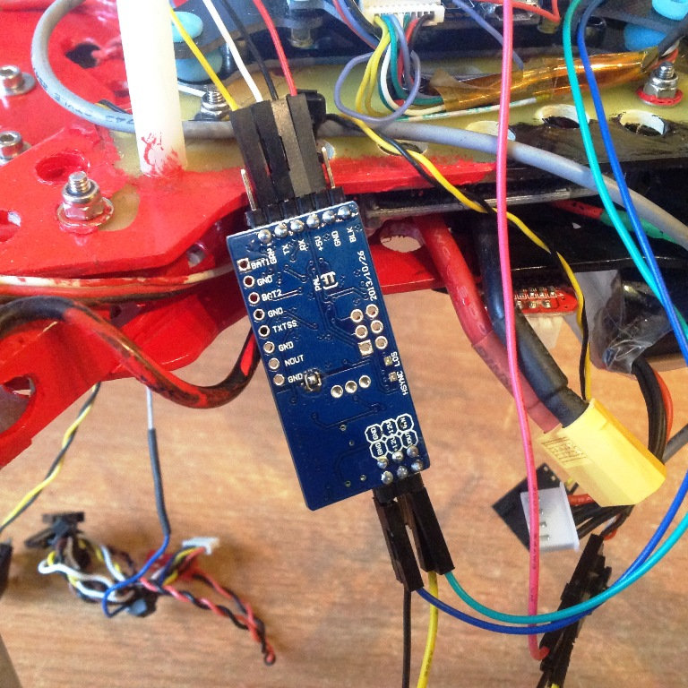
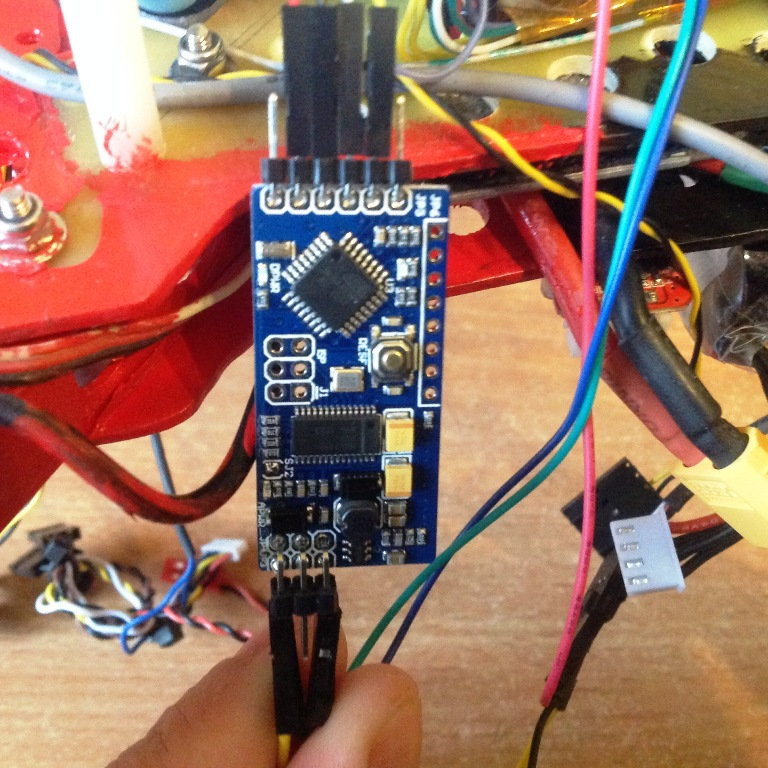
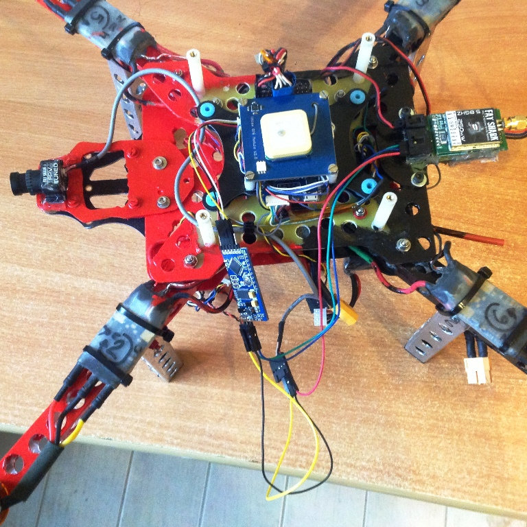
Le minomosd est connecté sur le serial3 de ma multiwii pro ez3
La caméra est connectée de la façon suivante:
Le fil rouge au 5V caméra et 5V TX, le fil jaune au Vin de l'OSD et le noir au Gnd de l'osd
Le fil vert au Vout de l'osd et entrée signal du TX
Le fil bleu au gnd de l'osd et entrée gnd du TX
J'ai également fait l'essai avec ma caméra xiaomi yi (signal et gnd seulement) mais pas mieux.
Voilà les photos du montage


Le minomosd est connecté sur le serial3 de ma multiwii pro ez3
La caméra est connectée de la façon suivante:
Le fil rouge au 5V caméra et 5V TX, le fil jaune au Vin de l'OSD et le noir au Gnd de l'osd
Le fil vert au Vout de l'osd et entrée signal du TX
Le fil bleu au gnd de l'osd et entrée gnd du TX
J'ai également fait l'essai avec ma caméra xiaomi yi (signal et gnd seulement) mais pas mieux.
-
Dehas
- Administrateur du site
- Messages : 16171
- Enregistré le : ven. 3 juin 2011 12:50
- Réputation : 5
- Localisation : Saint Dié des Vosges
- Genre :
- Contact :